


 Sign In
 Create Account


 View Garage
I installed an LC-1 wideband sensor in my car this weekend, and while Speedy’s video remains the definitive reference for this install, mine was different enough that I thought other people might find it helpful. First off, it didn’t take me the 20+ hours and several days because I didn’t install gauges. Since I’m using the wideband strictly for tuning, and I’m not running boost yet, I don’t need a constant readout of AFR. The info I need will be displayed and logged by the Trinity when it’s hooked up to the LC-1, but once everything’s dialed in I don’t need to constantly see it. Because I was installing just the wideband, I didn’t need to install the Cirkit Boss. This also simplified things, and so my total time for installation was probably about 3-5 hours (hard to say, because I kept getting distracted by other stuff).
So if you’re about to install a wideband without gauges, start by watching Speedy’s video. This will make a lot more sense.
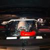
The LC-1 comes with 6 wires all in a rubber sheath. The first thing I did was slice this sheath open, because I needed to split up the wires to send to different parts of the engine bay. It’s important to keep all the ground wires as close as possible. Best case is to solder them onto the same lug, second best would be to solder them to individual lugs, but attached to separate ground points. What you don’t want to do is solder them to individual lugs and then attach those lugs to the SAME ground point. Corrosion developing between the lugs will introduce noise into the signal. So I separated the red, blue, white and black wires, then soldered the white, blue, and black wires onto the same lug. I ran those 4 wires over to the TIPM (fuse box).
Speedy’s video mentions a special connector that he used to insert the power wire into the Diesel PCM fuse (fuse #5). Kenny gave me a part number for this connector: It’s a Molex 19420-0009. I ordered it from DigiKey, where I also got the 2.5 mm stereo cable, per the video. The connectors are only about 27 cents a piece. I recommend ordering a few, in case you make a mistake.
Another key piece of information that Kenny gave me was to use Pin #10. There are tiny numbers on the back of the harness connector that goes into the fuse box, and you can see them with a magnifying glass. Keep in mind, though, that this circuit is only hot with the engine RUNNING. Also, the molex connector needs to be pushed all the way in, its entire length. At first I didn’t have it pushed in far enough, and was wondering why I didn’t get a signal.
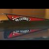
The next part I did differently was placement of the calibration LED. This part is optional, but having the button and LED make a lot easier to calibrate the sensor. The LED will also flash trouble codes or provide status information. What I did NOT want to do was drill into an interior trim panel for something that I was only going to use very infrequently under very specific circumstances that don’t even require me to be in the car. Instead, I placed the LED and calibration button in the front panel of the TIPM. This thing comes off really easily if you insert 2 screwdrivers into the tabs at the very top to release them, then slide the panel towards the fender. Once it was off the car it was very simple to drill the required holes. Another advantage of locating the LED and calibration button here is that the black wire passes right under this panel on its way to the ground point.
In hindsight, I wish I had placed the calibration button and light in the cockpit, like Speedy did. This makes it very easy to calibrate your sensor without even removing it from the vehicle, while driving. All you have to do is coast for a few seconds, until your AFR reads 22.4. At that point, your exhaust is only seeing free air, because the engine has cut fuel. Push the button, and you're calibrated.
An alternate method of free air calibrating without removing the sensor is to just do it after your car has been sitting for 48 hours. At that point, the air in the exhaust will have equalized with free air. The problem with this setup is that the car needs to be running to send power to the LC-1. So I would have to supply power to the LC-1 by means other than ignition on.
I located the body of the LC-1 pretty much where everyone else did. Zip ties, and you’re done. One thing I was careful about here, though, was to leave easy access to where the sensor connects to the unit.
I used the same grommet that everyone else did, and drilled a hole in the middle of it. I wasted a few minutes trying to pull the thing out through the engine bay before I realized that the lip is too big, and you have to remove it by pulling it rearwards into the cockpit.
LC-1’s used to ship with an exhaust bung and plug, so if you detached the sensor you can plug the hole in your exhaust. Mine didn’t come with the plug, and when I called Innovate to find out why, they said that they consider the wideband a “permanent installation” so the sensor should be always hooked up, and the plug is unnecessary. No big deal, any exhaust shop will have these things. Here’s a picture of the bung with plug. I got one because I thought I'd need to plug that hole when calibrating the sensor, but you really don't.
And with the sensor installed. When placing the bung, it's important to make sure it is horizontal or above. Meaning, don't put it below the 3 or 9 o'clock positions, otherwise condensation can settle onto the sensor and ruin it over time.
The second part of this install is getting the data from the LC-1 into your Trinity. Once again, Speedy’s video is the definitive authority on the subject. Unlike the video, I grounded the cable on the driver side fender.
I was a little concerned that this ground point is so far away from the other ones, on the other side of the engine bay. But I figured they were both attached to the body of the car (ideally they should be attached to the engine). I decided to try it out and see what kind of line loss I got, and if it was huge, I would attach the grounds directly to the engine block. Luckily, the line loss was only 0.15 volts, exactly what Speedy got in the video, and he grounded directly to the engine block. Score! Good enough for J, good enough for me. I didn’t have to move anything.
One thing I wasn’t clear on from the video was after calculating the line loss, where do you put the new upper value in: the LC-1, or the Trinity? J told me it was the Trinity. He didn’t do that in his video, hence my initial confusion, so I’m mentioning it here.
J had the brown wire attached to his AFR gauge, and the yellow one to the Trinity. Since I don’t have a gauge, but didn’t want to leave anything hanging, I went ahead and wired both the yellow and the brown wires (Analog 1 and Analog 2) up to the Trinity. It’s redundant, but I know where the wires are so I can always go get them if I want to wire up a gauge in the future. I can also have the Trinity display both a narrowband and wideband, although why I’d want to do that I have no idea.
I put the rubber sheath back on the wires just to hold them all together.
Then wire loom on top of it, and everything zip-tied into place.
J almost talked me out of doing this installation myself because of how long it took him. But when I realized my application was different from his, thus decreasing the time and difficulty, I thought I’d give it a shot. I’m getting better at electrical stuff, and this was a great exercise. I hope this write-up helps somebody else out who’s in a similar situation.
Addendum: since doing this write-up, I've installed the performance gauges like J did. I now have the 2nd analog output going to an Aeroforce Interceptor gauge. I never run both the Trinity or the Aeroforce at the same time, since they both use the DLC to pull PIDs. The Trinity is for logging and tuning, while the Aeroforce is for daily driving.


 Back to top


 That's what I was thinking too. I'm really not stressing about it.


